
Illinois Institute of Technology - Arch 497
Digital Design and Fabrication
Thomas J McLeish, Chris Palmer

This course explores the design and fabrication of architectural components in contemporary practice. We will investigate through the design and prototyping of a custom architectural component.
1. Survey of CAD/CAM use in architectural practice and component manufacturing.
2. Behavioral models of building structures using Structural analysis tools
3. Use of CAD tools to model building components for production.
4. Use of CAD tools to analyze structural properties of components.
5. Material properties and related fabrication constraints.
6. Current fabrication processes
7. Use of IIT owned CNC tools to fabricate architectural components
8. Rapid prototyping
The primary objective of this course is to expose students to new technologies used in architectural practice and component design and fabrication - such that they can include them within their architectural palette and have a meaningful dialogue with those construction team members who specialize in these trades.
Students successfully completing this course will demonstrate the following:
• An understanding of the broader implications of digital design and fabrication on architectural practice.
• An understanding of a variety of architectural materials and their use in digital fabrication.
• The ability to use 3D modeling tools to design, analyze, and fabricate an architectural component.
• The ability to prepare and transfer data between various modeling and fabrication tools.
Students will be required to write a research paper on a relevant topic, fabricate design studies of an architectural component, and produce a full-scale working prototype of a final design solution.
Structural Node
Student
Simon Fiedler
Design Sketch
The design sketch shows the lower connection node of a suspension truss. Trusses span in two directions, so that for cable connections for the truss and 4 cable connections for the diagonals are needed at one point. The shape of the node should follow the different force directions that are going from the cables to the strut.

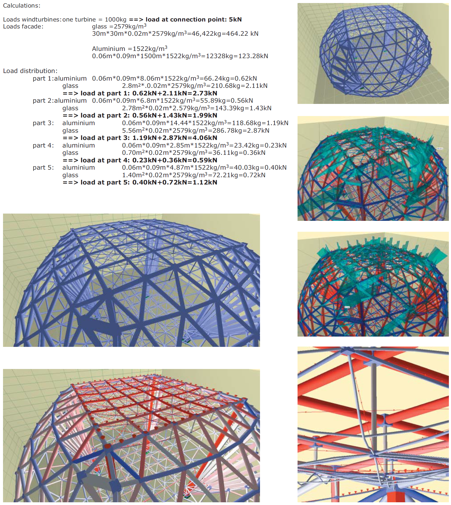
Structural Analysis
A structural analysis of the entire structural system was made to define the different forces on the detail point that should be designed. The loads of the glass roof and the facade structure were calculated and inserted on the designated location of the structure in Dr. Frames. Results were shown of the deformation, the force values, the strength of each forch, the strong moments and the strong shear loads.
3D Model
The detail node was built with Rhinoceros, a NURBS-based 3D model program. The pictures show renderings of the final model including all curved surfaces and holes for the pin connections between the cables and the connection point. The picture on the lower left shows the structure in its context with the detail point in the middle of the suspension truss at the top. The rendering on the lower right shows the detail point in its context with all connected cables around.

Structural Analysis
To improve the 3D model of the part created in Rhinoceros, it was exported to Autodesk Inventor for some structural analysis. The pictures and the tables show the results of that stress analysis. The force values were given by the earlier discussed Dr. Frames analysis of the entire structural system. Red colored parts show dangerous constellations and blue colored parts could be improved by taking away some material.

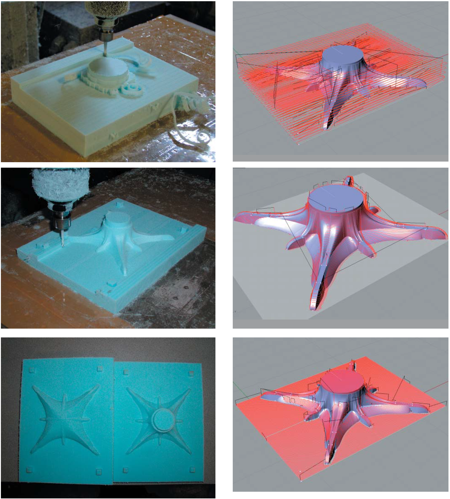
Mold Making
Three different paths were used to build the mold out of foam. A roughing path with a bigger bit to get rid of the material. The Z-level path is done by a smaller bit to get as close as possible to the final shape by cutting in a circle path from the inside to the outside and from the top to the bottom. The planar finish path creates the smooth surface that could be improved by adding another path perpendicular to the first and decreasing the offset of the bit per path.
Casting
The exact fitting of the mold into the wooden casting form is significant to prevent an offset of the two parts and to press the sand in every single edge. Before the casting process in this example, one big hole was made to bring the aluminum into the casting box and the air out of it. More material as needed will be used, because of the shrinking of metal by cooling down, and will be cut off in the finishing process.

Finishing
After the casting process, the material that is not part of the mock-up can be cut off. To get the exact fitting of the tube on the top a drilling machine with a rotating table was used to get sharp and exact edges. The entire model was finished with filling and drilling tools to get holes for the pin connection and to get a perfectly smooth surface of the model. The finish was made with a sandblasting process.
